You are here: Urology Textbook > Urologic examinations > Imaging > Principles of ultrasound imaging
Principles of Ultrasound Imaging in Urology
Ultrasound Waves
Definition:
Ultrasound waves are longitudinal mechanical waves with a frequency above 20,000 Hz; for diagnostic ultrasound, frequencies between 2–10 MHz (Megahertz) are used (Singer et al., 2006).
Creation of ultrasound waves:
The piezoelectric effect leads to an electric charge by mechanical stress on a quartz crystal. Ultrasonic waves can be generated with the reversed piezoelectric effect: alternating current from a high-frequency generator applied to a series of quartz crystals in the transducer.
Detection of the ultrasound echo:
The reflected ultrasonic waves (echo) generate a low voltage by deforming the piezoelectric crystal. The electric signal is amplified and computed: the time shift between generation and detection enables the assignment of the signal to a tissue depth.
Pulse echo principle:
The high frequency generator generates a short wave series (e.g., two periods, approximately 0.3–0.6 μ duration). After that, the piezoelectric crystal in the transducer serves as a detector for the reflected sound waves. The next pulse-echo cycle can only be started after receiving the echo from the selected maximum depth.
Resolution:
The axial imaging resolution (in the direction of the wave) depends on the frequency (e.g., 0.2–0.3 mm at 7.5 MHz). The higher the frequency, the better the resolution. The lateral imaging resolution depends on the geometry of the transducer and is highest in the focal zone. In a 7.5 MHz linear transducer, the lateral imaging resolution is 0.5–0.7 mm.
Interaction of Ultrasound Waves with Tissue
Sound waves propagate through tissue at a speed of about 1540 m/s. The ultrasonic waves are attenuated by various mechanisms (reflection, scattering, interference, and absorption). The lower the frequency of the ultrasound, the less the waves are attenuated by the tissue, and the better the ability to study deep regions.
Reflection:
At the interface of tissues with different densities, there is a partial or complete reflection of the ultrasound wave. The reflected (returning) wave is crucial in diagnostic ultrasound, providing information about the tissue structure.
Scattering:
A circular reflection wave is created if the ultrasound wave hits a small object. The interference of the scattered sound waves produces a grainy echo of actually homogeneous tissues (speckle-noise).
Refraction:
If the ultrasound wave hits an interface of tissues with different densities not at a right angle, the advancing non-reflected wave is deflected in its direction of propagation.
Absorption:
Loss of ultrasound wave energy due to friction, (minimal) heat is generated.
Artefacts in Medical Ultrasound Imaging
The interaction of ultrasound waves with tissues can lead to disturbances of the image structure, which do not correspond to the tissue anatomy. Knowledge of artifacts is helpful in diagnostics.
Noise:
The interference of scattered sound waves produces a grainy echo of actually homogeneous tissues (speckle noise). Another form of noise is multiple small reflexes in echo-free structures close to the transducer (bladder or liver cysts).
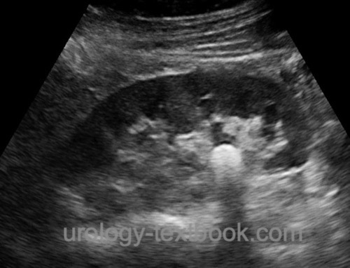
Acoustic shadow:
The dorsal echo-free area behind strongly reflecting or absorbing interfaces (stone, bone, air) [fig. kidney stone].
 |
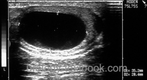
Acoustic enhancement:
Reduced ultrasound wave attenuation (increased through-transmission) in echo-poor tissues (cysts) leads to an enhancement of the posterior echo signal [fig. testicular cyst].
 |
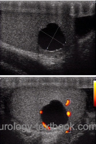
Edging artifact:
The edging artifact is a narrow shadow dorsal to the lateral boundary of a circular structure. The ultrasound wave is strongly attenuated by a combination of refraction and scattering caused by a tangential hit of the lateral edge [fig. testicular cyst with edging artifact].
 |
Reverberation:
Ultrasound waves can be reflected several times between two parallel interfaces, these additional reflection waves are computed according to the additional time to a greater depth.
Mirror image:
Strong reflecting interfaces may cause a specular reflection of the ultrasound wave leading to a mirror image.
Comet tail:
Strong repetitive echoes can disturb the image behind strongly reflective interfaces (reverberation artifact).
Side lobe artifact:
Side lobe artifact are arcuate reflections of highly reflective interfaces, which are only visible in hypoechoic structures. Echo reflections from the side lobe beam of the transducer cause the side lobe artifact.
Imaging Modes in Medical Ultrasound
The reflected echo can be displayed in different modes:
A-mode:
A-mode stands for amplitude modulation: the display of the echo in a diagram; the x-axis represents the depth, and the y-axis the echo intensity. The A-mode is not used anymore in modern ultrasound imaging.
B-mode:
B-mode stands for brightness modulation; the echo intensity is converted into brightness. Modern ultrasound imaging uses gray values.
2D Real-Time:
A linear array of transducers simultaneously scans a plane through the body. The echo is computed into a two-dimensional sectional image of the examined region. The frame rate of the image depends on the probe frequency and imaging depth and varies from a few to over 100 frames per second. 2D real time mode is the most commonly imaging mode used in urology, it can be combined with Doppler sonography.
M-mode:
M-mode stands for motion mode. The amplitude of the echo along a chosen line is shown on the y-axis, the x-axis represents the time. The M-mode has a high frame rate and is excellent for imaging fast-motion sequences of moving organs (e.g., heart valve or ventricular wall).
D-mode:
D-mode stands for Doppler mode. The Doppler effect is used to visualize the blood flow; see next section Doppler ultrasound.
Ultrasound Transducer Types
Linear transducer:
The linear arrangement of the piezoelectric crystals produces a rectangular beam shape. Linear transducers offer a high near-field resolution and use frequencies around 7,5 MHz.
Convex transducers:
Convex or curved array transducers have a curved linear arrangement of the piezoelectric crystals, reducing the footprint of the probe and producing a wide convex beam with an acceptable near-field resolution. Convex transducers are useful for imaging the abdominal cavity and use 2,5–5 MHz frequencies.
Sector array transducers:
The arrangement of the piezoelectric crystals produces a triangular beam (slice-of-pie shape with a field of view near 90 degrees. The near-field resolution is poor, sector array transducers have the smallest footprint and are used for imaging deep structures in the thorax and abdomen.
| Semen analysis | Index | Doppler ultrasound |
Index: 1–9 A B C D E F G H I J K L M N O P Q R S T U V W X Y Z
References
Singer u.a. 2006 SINGER, Eric A. ; GOLIJANIN, Dragan J. ; DAVIS, Robert S. ; DOGRA, Vikram: What’s new in urologic ultrasound?In: Urol Clin North Am
33 (2006), Aug, Nr. 3, S. 279–286
 Deutsche Version: Grundlagen der Ultraschall Untersuchung (Sonographie)